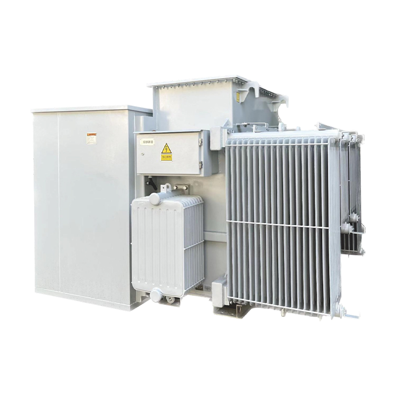
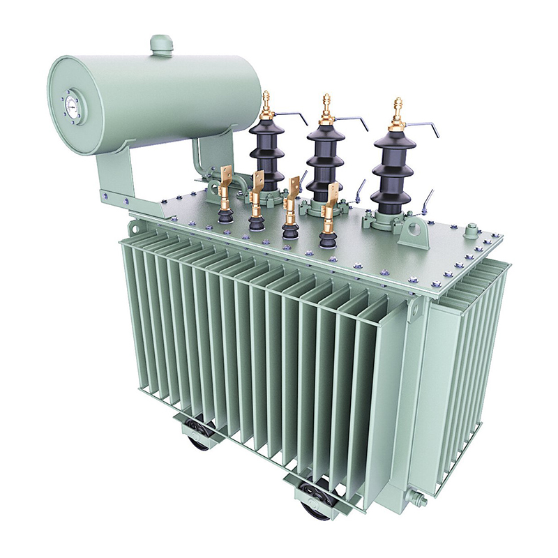
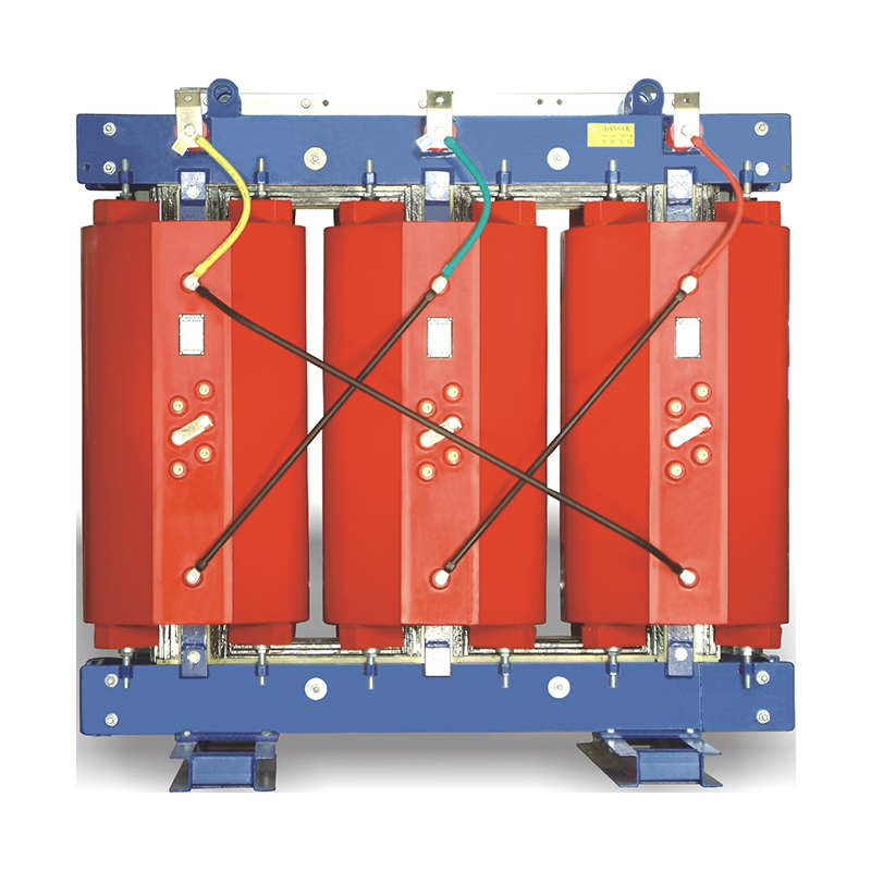
Differential protection is a primary safeguard for
power transformers, designed to quickly detect internal faults (e.g., winding short circuits, ground faults) by comparing the current entering and leaving the transformer. Unlike overcurrent or overvoltage protection, differential protection offers high sensitivity and selectivity, tripping the circuit breaker within milliseconds of fault detection. Its operation is based on Kirchhoff's current law (KCL), which states that the sum of currents entering a closed loop (in this case, the transformer) should be zero under normal conditions.
In a power transformer, current transformers (CTs) are installed on both the primary and secondary sides. The CTs convert high - voltage and high - current signals into measurable low - current signals. Under normal operation or external faults (e.g., faults outside the protected zone), the currents measured by the primary and secondary CTs are in balance, resulting in a zero or near - zero differential current (Id) at the protection relay:Id=I1−I2≈0
where I1 is the current from the primary - side CT and I2 is the current from the secondary - side CT.
However, during an internal fault (such as a turn - to - turn short circuit within the transformer windings), the current balance is disrupted. Fault currents flow through the fault path, causing a significant differential current (Id) that exceeds the relay's operating threshold (Iop). Once Id>Iop, the differential protection relay triggers the circuit breaker to isolate the faulty transformer.
Ratio Matching: CTs on the primary and secondary sides must have appropriate turns ratios (n1 and n2) to ensure current equivalence after transformation. The ratio should satisfy n1I1=n2I2 under normal conditions.
CT Saturation: During high - magnitude external faults, CTs may saturate, leading to unequal secondary currents and false differential currents. To mitigate this, high - quality CTs with high knee - point voltages and anti - saturation designs are used.
The restraint characteristic (also known as the braking characteristic) is introduced to prevent differential protection from mis - tripping during external faults or inrush currents (e.g., during transformer energization). These conditions can generate large currents that might incorrectly trigger the protection if not properly managed. The restraint mechanism adjusts the operating threshold (Iop) based on the magnitude of the restraint current (Ir), which is typically the sum of the primary and secondary currents:Ir=∣I1∣+∣I2∣
This is the most common type. The operating threshold Iop is a linear function of the restraint current Ir, defined by the equation:Iop=KrIr+Iop0
where:
Kr is the percentage restraint coefficient (usually 0.2–0.6), which determines the slope of the restraint line. A higher Kr provides stronger restraint against false trips.
Iop0 is the minimum operating current (a fixed value, e.g., 0.2–0.5 A), ensuring protection sensitivity for low - level internal faults.
The percentage restraint characteristic creates a "restraint zone" in the Id−Ir plane. For points below the restraint line (Id<KrIr+Iop0), the protection remains non - operative. When Id exceeds this line, the relay trips.
This advanced version uses multiple linear segments with different restraint coefficients (Kr1, Kr2) to improve performance. For example:
A lower Kr1 (e.g., 0.2) is applied for small restraint currents to maintain high sensitivity for internal faults.
A higher Kr2 (e.g., 0.6) is used for large restraint currents to prevent false trips during external faults or inrush conditions.
Transformer inrush currents contain significant harmonic components, especially the second - harmonic (2f) component. Differential protection relays can be configured to block tripping when the ratio of the second - harmonic current (I2f) to the fundamental - frequency current (If) exceeds a set threshold (e.g., 15–20%). This feature effectively suppresses unwanted tripping during energization.
During an internal fault, the differential current Id increases rapidly, while the restraint current Ir remains relatively low. As a result, the operating point (Id,Ir) moves above the restraint line in the Id−Ir plane, triggering the protection. The high sensitivity of differential protection ensures fast fault isolation, minimizing damage to the transformer.
External faults can cause high - magnitude currents in the primary and secondary CTs. These currents create a large restraint current Ir, which, combined with the percentage or multi - slope restraint characteristic, increases the operating threshold Iop. Consequently, the differential current Id (usually small due to CT mismatch or saturation effects) remains below the elevated Iop, preventing false tripping.
Transformer inrush currents occur when a transformer is energized. These currents can reach 5–10 times the rated current and contain high - amplitude second - harmonic components. The harmonic restraint feature blocks the differential protection until the inrush current decays and the I2f/If ratio drops below the threshold.
Sensitivity vs. Security: A lower Kr improves sensitivity to small internal faults but increases the risk of false trips. Engineers must balance these factors based on the transformer's rating, system configuration, and CT performance.
CT Error Compensation: Accounting for CT ratio errors and saturation effects during coefficient selection is crucial to avoid incorrect restraint settings.
Differential protection should be coordinated with backup protections (e.g., overcurrent protection) to ensure reliable fault clearance. Backup protections operate with longer time delays to allow differential protection to act first during internal faults.
IEEE C37.110: Provides guidelines for the application, setting, and testing of differential protection for power transformers.
IEC 60044 - 8: Specifies requirements for electronic current transformers (ECTs) used in differential protection systems, enhancing accuracy and anti - saturation capabilities.
Scenario: A 110 kV transformer's differential protection tripped during a nearby line fault.
Analysis: High - magnitude fault currents caused saturation in the primary - side CT, resulting in unequal secondary currents and a false differential current.
Solution: Replacing the CT with a higher knee - point voltage model and adjusting the restraint coefficient Kr from 0.3 to 0.4 resolved the issue, preventing future false trips.
Digital and Adaptive Protection: Advanced numerical relays with adaptive restraint characteristics can adjust settings in real - time based on system conditions (e.g., load levels, fault types).
Multifunctional Integration: Combining differential protection with other functions (e.g., waveform analysis, harmonic monitoring) in intelligent electronic devices (IEDs) for comprehensive transformer health assessment.
Communication - Based Protection: Using high - speed communication networks (e.g., IEC 61850) to improve CT data synchronization and enhance the performance of differential protection in complex grid environments.
Differential protection, with its reliance on the principle of current balance and sophisticated restraint characteristics, is a cornerstone of transformer protection. Understanding its operation, analyzing restraint curves, and carefully setting parameters are essential for ensuring the reliability and security of power systems. Continued advancements in technology will further optimize the performance of differential protection, safeguarding critical transformer assets in modern power grids.


