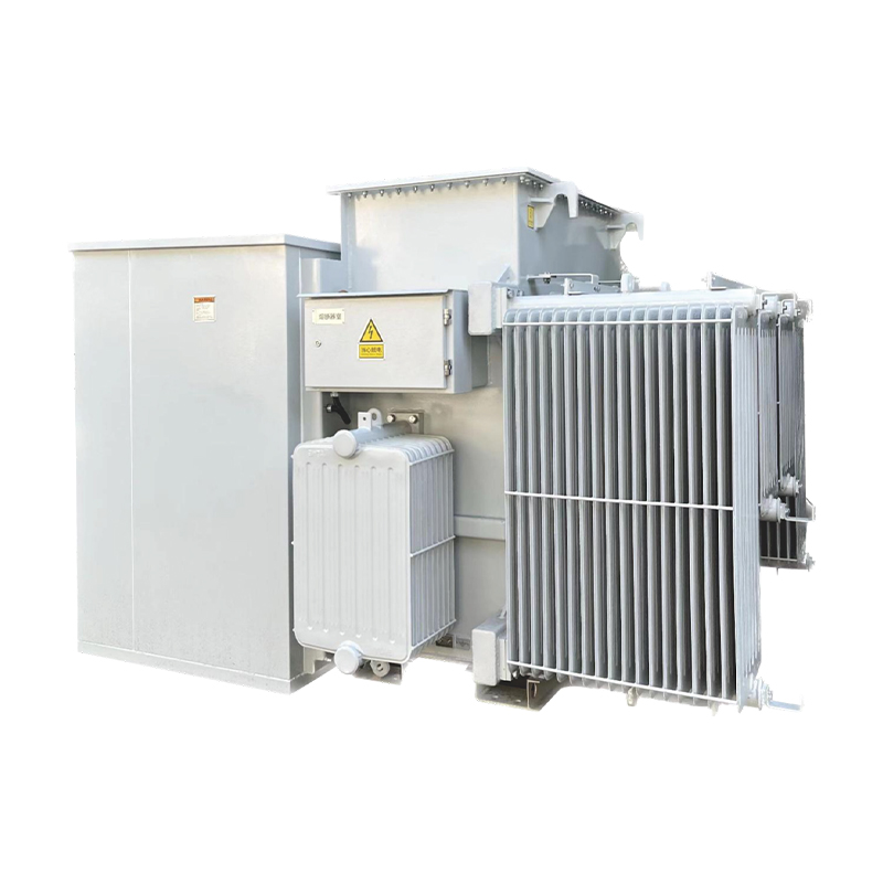
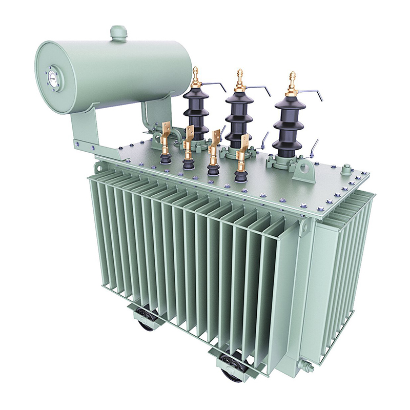
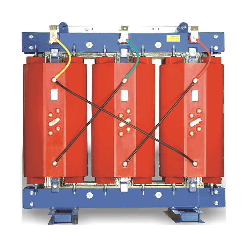
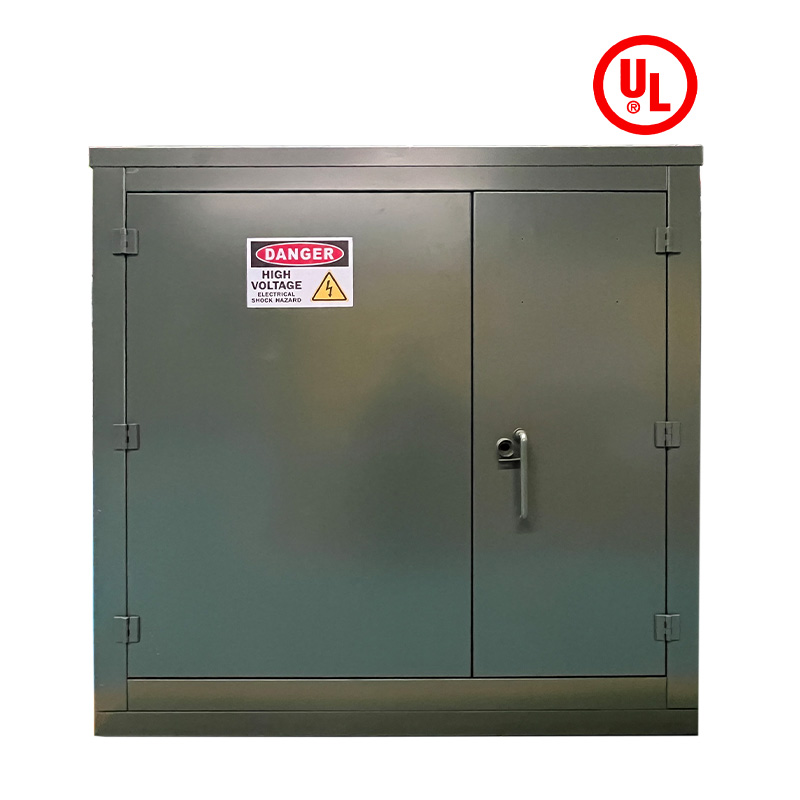
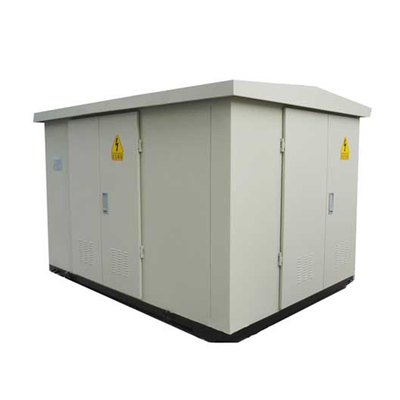
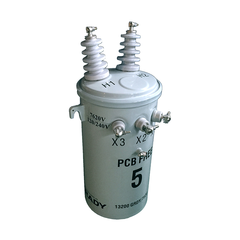
The global energy transition, driven by decarbonization goals and advancements in renewable energy technologies, has led to a rapid surge in distributed generation (DG) installations. DG systems—including solar photovoltaic (PV) arrays, wind turbines, small-scale gas turbines, and energy storage systems (ESS)—are typically connected to low-voltage (LV) or medium-voltage (MV) distribution networks, closer to end-users. While DG enhances energy resilience, reduces transmission losses, and lowers carbon emissions, its integration fundamentally alters the traditional unidirectional power flow in distribution grids. Power transformers, as critical assets linking different voltage levels, are particularly affected by these changes. This study examines how DG integration modifies transformer load profiles, thermal behavior, efficiency, and operational reliability, supported by technical analyses and case studies.
DG systems vary significantly in output 特性 (output characteristics):
Intermittent sources: Solar PV and wind turbines exhibit variable output dependent on weather conditions, with fluctuations occurring over minutes to hours .
Dispatchable sources: Combined heat and power (CHP) units and gas turbines can adjust output to match demand, providing more stable power .
Hybrid systems: Integrate ESS (e.g., lithium-ion batteries) to mitigate intermittency, enabling smoother power injection into grids .
By 2030, global DG capacity is projected to exceed 1.5 TW, with solar PV accounting for ~60% of new installations . This growth necessitates re-evaluation of transformer design and operation paradigms.
Conventionally, distribution transformers operate with unidirectional power flow: receiving bulk power from transmission grids and supplying it to downstream loads. Their load profiles follow diurnal patterns, with peaks during morning/evening hours and minima at night. DG integration introduces bidirectional flows: during high DG output (e.g., midday for PV), excess power may reverse direction, flowing from LV/MV networks back to higher-voltage grids. This reverses the transformer’s traditional role, transforming it into a bidirectional energy hub .
DG integration flattens or inverts traditional load curves. For example:
Residential feeders with high PV penetration: During midday, PV generation often exceeds local demand, causing net power export. This creates a "valley" in the transformer’s import load, with possible reverse loading (negative load) .
Commercial areas with rooftop PV: Peak demand (afternoon) may partially overlap with peak PV output, reducing the transformer’s net load by 30–50% .
A study by the IEEE Power & Energy Society (PES) on a 10 MVA distribution transformer in California showed that PV integration (40% penetration) reduced peak load from 8.2 MVA to 5.7 MVA but introduced 1.2 MVA reverse power flow during midday .
Reverse power flow (RPF) challenges transformer design assumptions:
Voltage regulation: Traditional transformers use on-load tap changers (OLTCs) to maintain secondary voltage under forward load. RPF can cause overvoltage on the primary side, forcing OLTCs to operate more frequently (up to 5x daily in high-penetration scenarios), increasing wear .
Insulation stress: RPF reverses electric field distribution in transformer windings. While modern transformers are designed for limited bidirectional operation, prolonged RPF (e.g., >6 hours/day) may accelerate insulation degradation, particularly in older units (>20 years) .
Intermittent DG (e.g., wind, PV) introduces rapid load fluctuations:
Ramp rates: PV output can drop by 50% in 10 minutes during cloud cover, causing transformer load to swing from -2 MVA (export) to +4 MVA (import) .
Harmonic distortion: Power electronic interfaces in DG systems (e.g., inverters) generate harmonics (5th, 7th, 11th orders). These harmonics increase eddy current losses in transformer cores, raising operating temperatures by 5–10°C .
A simulation of a 2 MVA transformer with 50% PV penetration showed total harmonic distortion (THD) rising from 2% (no DG) to 8–12%, exceeding IEEE 519 limits (5% for MV systems) .
Transformer lifespan is strongly tied to winding temperature: each 6°C increase above the design limit (typically 65°C for mineral oil-immersed units) halves insulation life . DG integration affects thermal dynamics through:
Uneven load distribution: RPF creates non-uniform current density in windings, leading to localized hot spots (e.g., 10–15°C higher than average winding temperature) .
Reduced cooling efficiency: Traditional transformers rely on natural convection under forward load. RPF reverses oil circulation patterns, impairing heat dissipation in some core regions .
Field data from a 5 MVA transformer in Germany (30% wind DG penetration) showed hot-spot temperatures reaching 82°C (vs. 68°C without DG), accelerating insulation aging by an estimated 30% .
DG-induced load variability increases thermal cycling:
Daily cycles: Temperature swings of 20–30°C (vs. 10–15°C in traditional grids) strain insulation materials, causing mechanical fatigue .
Start-stop cycles: Dispatchable DG (e.g., CHP units) frequently switching on/off introduces transient currents, generating short-term thermal spikes (up to 10°C in 5 minutes) .
A study by CIGRE Working Group 12.24 found that transformers in DG-rich grids experience 2–3x more thermal cycles, reducing their design lifespan (40 years) by 15–25% .
Transformer losses consist of:
Core losses (no-load losses): Constant, dependent on voltage and frequency.
Copper losses (load losses): Proportional to the square of current, varying with load .
DG integration modifies loss profiles:
Reduced average load: Lower net load reduces copper losses by 10–20% in high-penetration scenarios .
Harmonic losses: Harmonics from DG inverters increase copper losses by 5–15% due to skin and proximity effects .
For a 10 MVA transformer with 40% PV penetration, annual copper losses decreased by 12%, but harmonic-related losses increased by 8%, resulting in a net 4% reduction in total losses .
Traditional transformers are optimized for 50–75% load, where efficiency peaks (typically 96–98%). DG integration shifts operating points to lower loads (20–40%) or reverse power, where efficiency drops by 2–5% . This inefficiency is exacerbated by light loading during high DG output, reducing overall grid energy efficiency.
Bidirectional-optimized transformers: Reinforced insulation, improved cooling systems (e.g., forced oil circulation), and OLTCs rated for frequent reverse operation .
Harmonic-resistant cores: Use of amorphous metal alloys reduces eddy current losses from harmonics by 30–40% compared to traditional silicon steel .
DG curtailment: Controlled reduction of DG output during peak reverse flow to limit RPF to <20% of transformer rating .
ESS integration: Batteries absorb excess DG generation, smoothing load fluctuations and reducing thermal cycles. A 500 kWh ESS in a Dutch neighborhood reduced transformer load variability by 60% .
Advanced monitoring: IoT sensors (e.g., fiber-optic temperature probes, smart meters) enable real-time tracking of transformer load, temperature, and harmonics, supporting predictive maintenance .
Dynamic rating: Adjusting transformer load limits based on real-time conditions (e.g., ambient temperature, DG output) increases utilization by 15–20% without compromising safety .
Updated standards: IEEE C57.12.00 (2024) now includes guidelines for transformers in DG-rich grids, specifying RPF tolerance and harmonic immunity .
A 20 MVA MV/LV transformer serving a residential area with 3 MW of rooftop PV (40% penetration) was monitored over 12 months:
Reverse power flow occurred 4 hours/day (midday), peaking at 5 MVA (25% of rating).
Hot-spot temperature increased by 12°C, with thermal cycles doubling compared to pre-DG levels.
After installing a 1 MWh ESS, RPF was reduced by 70%, and thermal cycles decreased by 45% .
A 5 MVA transformer in a wind-rich rural network (2.5 MW wind turbines) exhibited:
Harmonic distortion (THD) of 9.2% due to wind inverter switching.
Annual copper losses increased by 8% due to harmonics, offsetting 5% savings from lower average load.
Upgrading to a harmonic-resistant transformer reduced losses by 11% .
High DG penetration (>50%): May require transformers with full bidirectional capability and zero-sequence current management to handle unbalanced DG integration .
Electrification of transport: EV charging stations, often colocated with DG, will introduce additional load variability, demanding transformer designs that accommodate both DG exports and EV imports .
AI-driven optimization: Machine learning algorithms will predict DG output and load, enabling proactive transformer load management to minimize aging .
Key challenges include balancing DG growth with transformer reliability, updating aging infrastructure, and harmonizing international standards for DG-integrated grids.
Distributed generation integration profoundly reshapes power transformer load characteristics, introducing bidirectional flows, harmonic distortion, and thermal cycling that challenge traditional operation paradigms. These changes can reduce transformer lifespan, lower efficiency, and increase operational risks if unmanaged. However, through adaptive transformer designs, smart grid technologies, and proactive planning, the negative impacts can be mitigated. As DG penetration continues to rise, collaboration between utilities, manufacturers, and policymakers will be critical to developing resilient, efficient, and sustainable distribution networks. Future research should focus on next-generation transformer materials (e.g., nanocomposite insulators) and AI-based predictive maintenance to ensure reliable operation in highly renewable grids.


