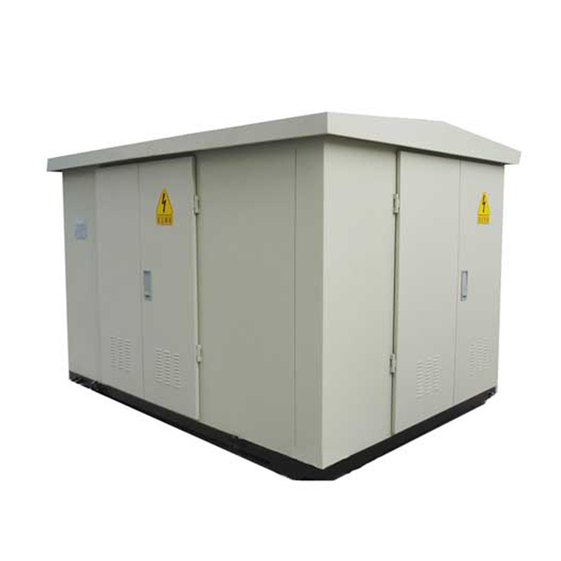
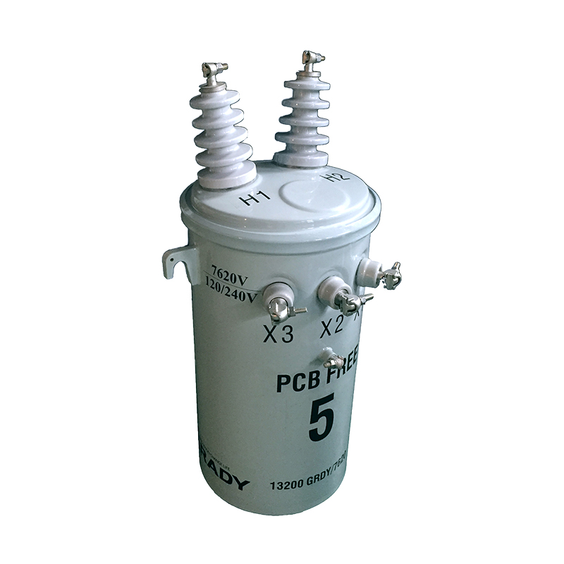
Parallel operation of
power transformers refers to the practice of connecting two or more transformers to the same primary and secondary busbars to share electrical loads. This configuration is widely adopted in power systems due to its advantages: improved reliability (via redundancy), enhanced flexibility in load management, simplified maintenance (allowing one transformer to operate while others are serviced), and optimized efficiency (matching transformer capacity to varying load demands). However, improper parallel operation can lead to excessive circulating currents, uneven load distribution, and even equipment damage.
This article systematically elaborates on the essential conditions for safe and efficient parallel operation of power transformers, followed by detailed protection coordination strategies to mitigate risks such as overloads, internal faults, and circulating currents. The analysis integrates technical standards (e.g., IEEE C57.12.00, IEC 60076) and practical engineering insights to provide a comprehensive guide for power system designers and operators.
For transformers to operate in parallel safely and efficiently, the following conditions must be met. Deviations from these conditions can cause operational issues, ranging from reduced efficiency to catastrophic failures.
The primary and secondary voltage ratios of all parallel-connected transformers must be identical. The voltage ratio (K) is defined as the ratio of primary rated voltage (V₁) to secondary rated voltage (V₂) (K = V₁/V₂).
Rationale: If transformers with different voltage ratios are paralleled, a circulating current (I_circulating) is generated in the closed loop formed by their secondary windings, even when no external load is connected. This current arises due to the voltage difference (ΔV) between the secondary terminals of the transformers:
ΔV = V₂₁ - V₂₂
I_circulating = ΔV / (Z₁ + Z₂)
where Z₁ and Z₂ are the impedances of the two transformers.
Impact: Circulating currents cause unnecessary power losses (I²R), overheating, and reduced efficiency. In extreme cases, they can exceed rated current, triggering false tripping of protective devices.
Allowable Deviation: To limit circulating currents to ≤5% of rated current, the voltage ratio difference between transformers is typically restricted to ±0.5% (per IEEE C57.12.00). This ensures ΔV is small enough to avoid significant performance degradation.
Transformers in parallel must have the same phase shift (i.e., identical vector groups) and correct polarity.
Phase Shift: The vector group (e.g., Dyn11, YNd1) determines the phase relationship between primary and secondary voltages. A mismatch in vector groups introduces a phase difference (e.g., 30° or 180°) between the secondary voltages of paralleled transformers, even if their voltage ratios are equal. This phase difference creates a large ΔV (up to 2 times the rated secondary voltage in severe cases), resulting in massive circulating currents that can instantly damage windings.
Polarity: Incorrect polarity (reverse connection of primary or secondary leads) inverts the voltage phase, creating a 180° phase difference. This is equivalent to a vector group mismatch and leads to destructive 环流.
Critical Requirement: Unlike voltage ratio deviations, phase shift or polarity mismatches are unacceptable under any circumstances. Transformers must be rigorously tested (e.g., using phase sequence meters) to confirm identical vector groups before parallel operation.
The percentage impedance voltage (Z%)—the voltage drop (expressed as a percentage of rated voltage) when rated current flows through the transformer—must be identical for all paralleled transformers.
Rationale: Z% determines how load current is shared between transformers. For two transformers in parallel, the load current division follows the inverse ratio of their Z%:
I₁/I₂ = Z₂%/Z₁%
If Z₁% ≠ Z₂%, the transformer with lower Z% will carry a larger share of the load, potentially exceeding its rated capacity (overloading), while the other operates underloaded.
Impact: Overloading causes insulation degradation, increased temperature rise, and reduced lifespan. Underloaded transformers operate at lower efficiency (since iron losses dominate at light loads).
Allowable Deviation: A maximum difference of ±10% in Z% is permitted in practice (e.g., transformers with Z% of 5% and 5.5% can be paralleled). This ensures load imbalance remains within safe limits (≤10% of rated current for either transformer).
While not a strict technical condition, the rated capacities of paralleled transformers should ideally be within a 1:3 ratio (e.g., 10 MVA and 30 MVA are acceptable, but 10 MVA and 50 MVA are not).
Rationale: A large capacity mismatch exacerbates load-sharing issues, even if Z% is balanced. The smaller transformer may still carry a disproportionately high load during peak conditions, leading to overloads.
Practical Guideline: Utilities often limit the capacity ratio to 1:2 to simplify protection coordination and ensure stable load distribution.
Parallel operation introduces unique challenges for protection systems, as faults in one transformer can affect others, and load redistribution during outages requires coordinated tripping to avoid cascading failures. The primary goals of protection coordination are:
Detect internal faults (e.g., winding short circuits) in individual transformers and isolate them rapidly.
Prevent overloads in remaining transformers after one is tripped.
Avoid unnecessary tripping of healthy transformers during external faults or load fluctuations.
Each transformer in a parallel bank must be equipped with primary protection to detect internal faults, ensuring rapid isolation to minimize damage.
Differential protection is the gold standard for detecting internal faults (e.g., phase-to-phase, phase-to-ground, or 匝间短路) in transformers. It operates based on the current difference between the primary and secondary windings.
Principle: Current transformers (CTs) installed on the primary and secondary sides of the transformer measure currents I₁ and I₂. The protection relay compares the vector sum of these currents (I_diff = I₁ - I₂). Under normal conditions, I_diff ≈ 0 (accounting for magnetizing current). During an internal fault, I_diff increases significantly, triggering the relay to trip the transformer’s circuit breakers.
Coordination in Parallel Banks:
CTs must have identical ratios and accuracy classes to ensure balanced current measurement.
The differential relay for each transformer must be set to ignore circulating currents between paralleled units (which do not create a net I_diff for individual transformers).
Time delays are avoided (instantaneous operation) to limit fault duration, but care is taken to prevent tripping due to transient inrush currents during energization (using harmonic restraint or magnetizing inrush blocking).
Buchholz relays are used in oil-immersed transformers to detect incipient faults (e.g., insulation degradation, core overheating, or minor oil leaks) that may not be visible to differential protection.
Operation: The relay is mounted in the pipe between the transformer tank and oil conservator.
Light gas alarm: Gas bubbles generated by incipient faults rise to the relay, displacing oil and actuating a float switch, triggering an alarm (no tripping).
Heavy gas trip: A severe fault (e.g., winding short circuit) produces a large volume of gas or oil flow, tripping a second float switch to isolate the transformer.
Coordination: Heavy gas trips are instantaneous and take priority over other protections, as they indicate catastrophic internal failures. Light gas alarms trigger maintenance checks but do not affect parallel operation.
Backup protection safeguards against primary protection failures, while overload protection prevents overheating during load redistribution.
Overcurrent relays are installed on the secondary side of each transformer to detect excessive currents caused by external faults (e.g., downstream short circuits) or overloads.
Setting Considerations:
Time grading: Relays are coordinated with downstream feeder protections to ensure selectivity. For example, a transformer overcurrent relay may have a time delay of 0.5s, while a feeder relay trips in 0.2s for the same fault current.
Load redistribution: When one transformer is tripped, the remaining units must carry the full load. Overcurrent relays for the remaining transformers are set with a higher pickup current (120–150% of rated current) and a longer time delay (e.g., 5–10s) to allow manual load shedding before tripping.
Example: For two 20 MVA transformers in parallel (total capacity 40 MVA), if one trips, the remaining transformer must carry up to 40 MVA (200% of its rating). The overload relay is set to trip at 150% rated current after 10s, giving operators time to reduce load.
Earth fault protection detects phase-to-ground faults, which are common in power systems. It uses a residual current transformer (RCT) to measure the sum of three-phase currents (Iₐ + I_b + I_c), which is zero under normal conditions but non-zero during a ground fault.
Coordination: Earth fault relays are set to trip faster than overcurrent relays for ground faults, as these can cause insulation damage due to arcing. In parallel banks, the relay for each transformer is set to detect only faults within its own windings or connected feeders, avoiding false trips from faults in other units.
When one transformer in a parallel bank is tripped (due to fault or maintenance), the remaining units must absorb the load without exceeding their thermal limits. Protection systems must manage this transition smoothly.
Overload Relays with Time Delays: As mentioned, remaining transformers’ overload relays are set to tolerate temporary overloads (e.g., 150% for 10s). This allows operators to redistribute load manually (e.g., by starting a standby transformer or shedding non-critical loads).
SCADA Integration: Modern systems use SCADA (Supervisory Control and Data Acquisition) to automatically detect transformer trips and issue alarms. In advanced setups, load shedding of non-critical feeders (e.g., street lighting) is triggered if overload persists beyond the time delay.
When reconnecting a tripped transformer to the parallel bank, protective relays must prevent inrush current-induced tripping.
Strategies:
Phase synchronization: Ensure the transformer’s secondary voltage matches the busbar voltage (magnitude, phase, and frequency) before closing the circuit breaker.
Inrush current limiting: Use soft-energization techniques (e.g., controlled closing resistors) to reduce inrush currents, which can reach 6–8 times rated current and falsely trigger differential or overcurrent relays.
While proper parallel conditions minimize circulating currents, deviations (e.g., voltage ratio mismatch due to tap changer adjustment) can cause excessive 环流.
Detection: Circulating currents can be monitored using CTs installed in the parallel connection busbars. A dedicated relay trips the transformer if circulating current exceeds 10–15% of rated current for an extended period.
Prevention: Regular maintenance checks ensure voltage ratios and tap positions are consistent across all transformers. Automated tap changers (if installed) are synchronized to avoid mismatches.
Protection coordination for parallel transformers must adhere to international standards to ensure reliability and safety:
IEEE C57.12.00: Specifies requirements for power transformers, including guidelines for parallel operation and protection.
IEC 60076-5: Covers transformer protection, emphasizing differential and overcurrent schemes.
ANSI/IEEE C37.91: Provides recommendations for protective relaying in power systems, including parallel transformer banks.
In practice, protection engineers use software tools (e.g., ETAP, DIgSILENT PowerFactory) to simulate fault conditions, calculate relay settings, and verify coordination curves. Field testing (e.g., primary injection tests) is performed to validate settings before commissioning.
Renewable Energy Integration: Transformers paralleled with renewable sources (e.g., solar, wind) face variable load profiles. Protection systems must adapt to bidirectional power flow and harmonic distortions.
Digitalization: Smart relays with IoT capabilities enable real-time monitoring of transformer parameters (temperature, load current, gas levels), allowing predictive maintenance and dynamic protection setting adjustments.
Microgrids: In microgrid applications, parallel transformers often operate in islanded mode, requiring protection systems to handle both grid-connected and standalone scenarios.
Parallel operation of power transformers is a critical practice in modern power systems, offering flexibility and reliability. However, it requires strict adherence to conditions—equal voltage ratios, identical vector groups, matching Z%, and similar capacities—to avoid circulating currents and load imbalance.
Protection coordination strategies must be tailored to parallel configurations, integrating differential relays for internal faults, overcurrent/earth fault relays for backup protection, and time-delayed overload relays to manage load redistribution. By combining technical standards, advanced relaying technology, and systematic testing, engineers can ensure safe, efficient, and resilient operation of parallel transformer banks, supporting the stability of power grids worldwide.