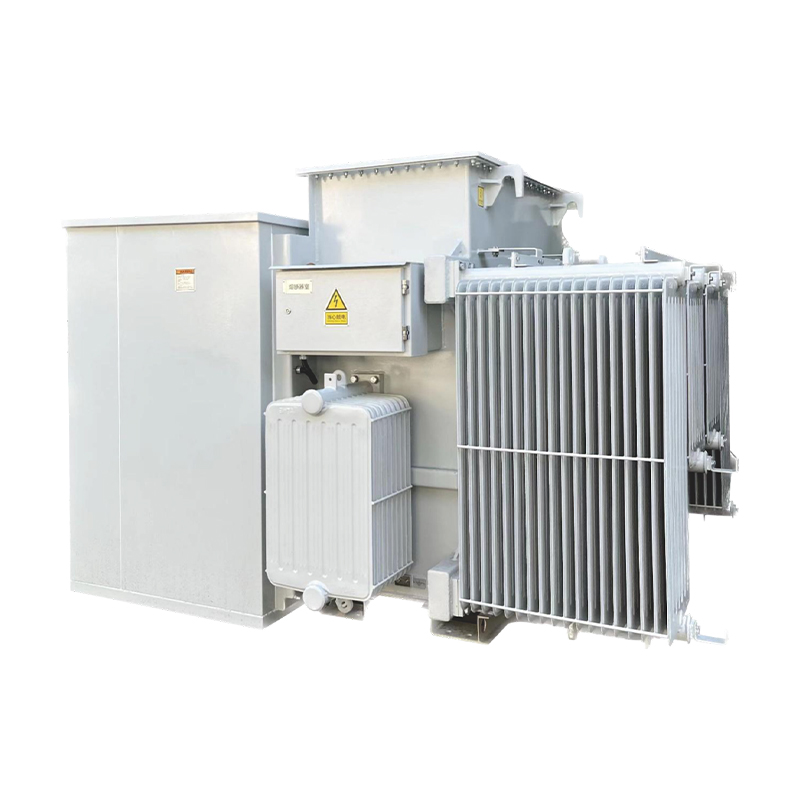
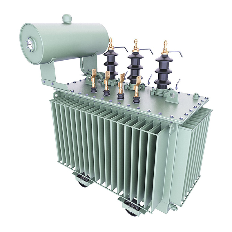
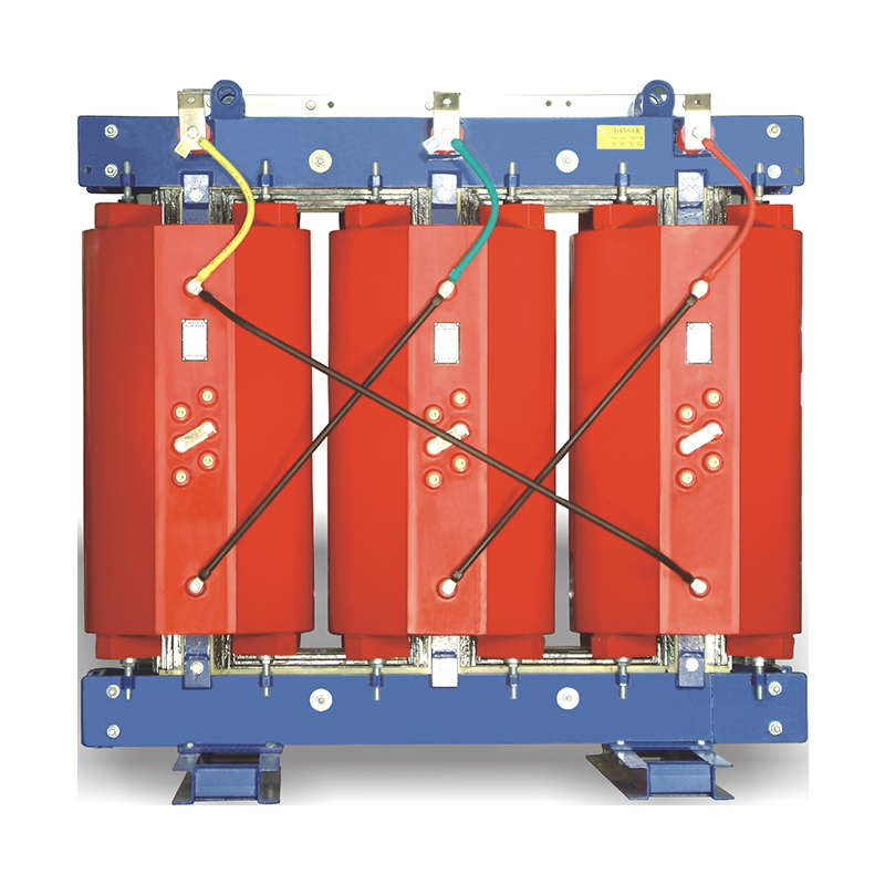
Inter-turn short circuits occur when the insulation between adjacent turns in a transformer winding fails, creating a parallel current path. This fault is one of the most critical threats to transformer reliability, accounting for ~30% of winding failures in
power transformers. Common causes include:
Insulation Aging: Degradation of paper/oil or epoxy insulation due to thermal stress, moisture, or chemical reactions.
Electrical Overstress: Lightning surges, switching transients, or harmonic voltages that breach insulation withstand limits.
Mechanical Damage: Winding deformation from short-circuit forces or improper installation.
Contamination: Particles or moisture in the insulation system leading to partial discharges (PD) and breakdown.
A shorted turn acts as a low-impedance loop, drawing excessive current (Isc) proportional to the number of shorted turns. For a winding with N turns and n shorted turns:Isc≈ZturnV∝N−nn
This causes unbalanced currents in multi-phase transformers, triggering differential protection relays.
Localized Overheating: Fault currents generate joule heating (I2R), raising temperatures in the shorted region. Infrared (IR) imaging may detect hotspots exceeding 100°C, compared to the normal winding temperature (≤95°C for oil-immersed transformers).
Oil Degradation: Overheating decomposes transformer oil, producing gases like methane (CH₄), ethylene (C₂H₄), and hydrogen (H₂). DGA (Dissolved Gas Analysis) ratios exceeding IEC 60599 codes (e.g., C₂H₄/C₂H₆ > 3) indicate thermal faults.
Vibration Amplification: Asymmetrical magnetic forces from shorted turns induce mechanical vibrations at frequencies of 2f (twice the power frequency). Vibration sensors may detect acceleration levels >5 g (normal: <2 g).
Winding Deformation: Prolonged faults can cause axial or radial displacement of windings, detected via frequency response analysis (FRA) or short-circuit impedance tests.
Arcing Noise: High-energy faults produce audible hissing or buzzing sounds due to partial discharges.
PD Activity: Insulation breakdown creates PD pulses, measurable via HFCT (High-Frequency Current Transformer) sensors or ultrasonic detectors. PD levels >100 pC are indicative of serious defects.
Compares resistance values between phases or windings. A deviation >2% from the average indicates possible shorted turns:ΔR=RavgRtest−Ravg×100%
Example: A 10 MVA transformer’s winding resistance shifts from 0.12 Ω to 0.11 Ω, suggesting a 5–8% turn loss.
Uses accelerometers to capture vibration signals at the tank surface. Fourier transform analysis of the signals reveals fault-related frequencies (e.g., 2f, 3f) with amplitude increases >30% compared to baseline.
| Fault Stage | Key Indicators | Risk Level |
|---|
| Incipient | PD <100 pC, gas levels <50 ppm (CH₄), ΔR <1% | Low |
| Developed | PD 100–500 pC, gas ratios approaching IEC limits, ΔR 1–3% | Medium |
| Critical | PD >500 pC, gas ratios exceeding IEC limits, ΔT >20°C | High |
Immediate Shutdown: For critical faults (e.g., smoking, explosive noises), isolate the transformer to prevent catastrophic failure.
Offline Testing: Perform FRA, DGA, and DC resistance tests to confirm fault location.
Repair or Rewinding: Replace damaged winding sections or rewind the entire winding if >10% of turns are shorted.
Insulation Refurbishment: Replace aged oil and paper insulation to prevent recurrence.
IEEE Std C57.12.90: Guidelines for transformer diagnostic testing.
IEC 60076-5: Specification for withstand voltage tests and partial discharge measurements.
ASTM D3612: Method for gas analysis in transformer oils.
Scenario: A utility transformer experienced tripping of the differential relay during a load increase.
AI-Driven Diagnostics: Machine learning models (e.g., convolutional neural networks) to analyze FRA and PD data for early fault detection.
IoT-Based Predictive Systems: Real-time integration of sensor data with cloud platforms for automated fault triaging.
Non-Destructive Testing (NDT) Advances: Use of terahertz imaging to visualize insulation defects without disassembly.
Inter-turn short circuit faults pose a significant risk to power transformer reliability, but timely diagnosis through a combination of electrical tests, thermal monitoring, and gas analysis can prevent catastrophic failures. By adhering to industry standards and leveraging advanced diagnostic technologies, operators can optimize maintenance strategies, extend transformer lifespan, and ensure the stability of power grids. Proactive fault management remains critical in maintaining the resilience of modern energy infrastructure.


