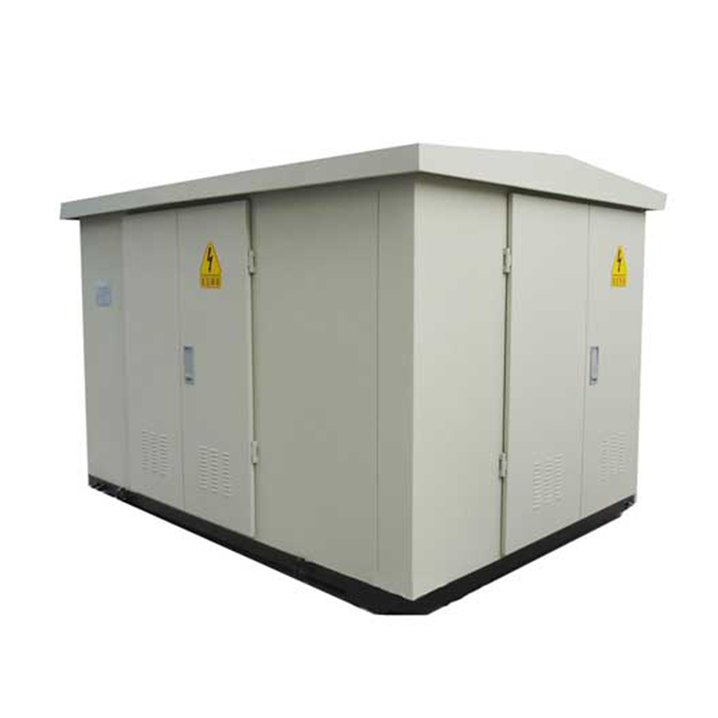
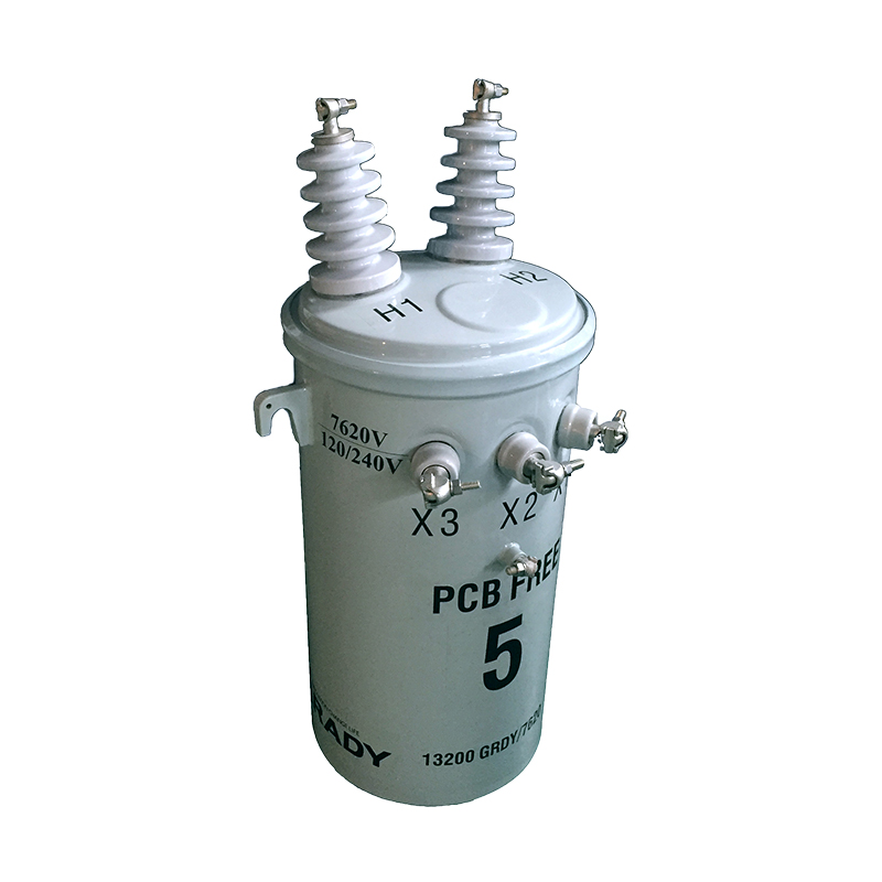
Electric vehicle (EV) charging stations are critical infrastructure for the mass adoption of electric mobility, and their reliable operation hinges on properly sized
power transformers. These transformers convert high-voltage grid power to the lower voltages required by charging equipment, making their capacity a key determinant of a station’s ability to meet demand, avoid overloads, and ensure efficiency. Unlike traditional transformers used in industrial or residential settings, EV charging station transformers must account for variable load profiles, diverse charging technologies (e.g., Level 2, DC fast charging), and future expansion needs. This article details the methodologies for calculating transformer capacity in EV charging stations, considering factors such as charging load characteristics, diversity, and operational constraints.
Before diving into calculation methods, it is essential to identify the primary factors that dictate transformer capacity in EV charging stations:
Charging Levels and Power Ratings:
Level 2 AC chargers (common in residential and commercial stations) typically operate at 208–240V AC, with power ratings ranging from 3.3 kW to 19.2 kW per port.
DC fast chargers (DCFC), used in public fast-charging stations, operate at higher voltages (200–920V DC) and power levels, ranging from 50 kW to 350 kW or more (e.g., Tesla Superchargers, Ultra-Fast chargers).
The total power demand of all chargers at a station directly impacts transformer sizing.
Number of Charging Ports:
The total number of active charging ports (both AC and DC) determines the maximum possible concurrent load. A station with 10 DCFC ports (each 150 kW) will have a vastly different load profile than one with 20 Level 2 ports (each 6.6 kW).
EV charging loads are inherently variable, as not all chargers operate at full capacity simultaneously. This "diversity factor"—the ratio of the actual maximum load to the sum of individual maximum loads—reduces the required transformer capacity. Key considerations include:
Peak vs. Off-Peak Hours: Charging demand often spikes during commuting hours (7–9 AM, 5–7 PM) or weekends, while remaining low overnight.
User Behavior: EV drivers may not fully charge their vehicles (e.g., topping up for 15–30 minutes at a fast charger), reducing average load.
Charging Duration: DCFCs have shorter dwell times (15–45 minutes) compared to Level 2 chargers (4–8 hours), affecting the coincidence of peak loads.
Voltage Regulation: Transformers must maintain stable output voltages (typically 480V or 600V for commercial applications) even under varying loads to avoid damage to charging equipment.
Ambient Temperature: Higher temperatures reduce transformer efficiency and load-carrying capacity. Transformers in hot climates may require derating (reduced capacity) to prevent overheating.
Future Expansion: Stations often plan for additional chargers, so transformers are sized to accommodate 10–30% future load growth.
Transformer capacity is typically rated in kilovolt-amperes (kVA), a unit that accounts for both real power (kW) and reactive power (kVAR). The core principle is to calculate the maximum apparent power demand of the charging station, adjusted for diversity, efficiency, and safety margins.
The total connected load is the sum of the maximum power ratings of all charging equipment, converted to kVA (assuming a power factor, typically 0.9 for modern chargers).
Formula:TCL=∑(Pcharger/PF)
Where:
Example:
A station with 8 Level 2 chargers (6.6 kW each) and 4 DCFCs (150 kW each):TCL=(8×6.6/0.9)+(4×150/0.9)TCL=(52.8/0.9)+(600/0.9)TCL≈58.67+666.67=725.34kVA
The diversity factor accounts for non-simultaneous operation of chargers. It is derived from historical data, industry standards, or empirical studies.
For Level 2 chargers in commercial settings (e.g., shopping malls), DF ranges from 0.3 to 0.5 (30–50% of ports operating simultaneously).
For DCFC stations, DF is higher (0.5 to 0.7) due to shorter charging times and more concentrated peak usage.
Mixed stations (AC + DC) typically use a weighted average DF.
Formula:Maximum Demand (MD)=TCL×DF
Example:
Using the previous station with a mixed DF of 0.6:MD=725.34kVA×0.6≈435.2kVA
Transformers are not 100% efficient, and their capacity is derated under certain conditions:
Efficiency Loss: Typical transformer efficiency is 95–98% at full load. To account for losses, the apparent power demand is divided by efficiency (η):Adjusted Demand=MD/η
Temperature Derating: Transformers operated above 30°C (ambient) require derating. For example, a transformer rated for 500 kVA at 30°C may be derated by 2% per °C above 30°C.
Safety Margin: A 10–20% safety margin is added to accommodate transient loads (e.g., sudden simultaneous charging) or minor expansions:Required Capacity=Adjusted Demand×(1+Safety Margin)
Example:
Using 96% efficiency (η=0.96) and a 15% safety margin:Adjusted Demand=435.2/0.96≈453.33kVARequired Capacity=453.33×1.15≈521.3kVA
The transformer would be sized to the next standard kVA rating (e.g., 630 kVA, a common industrial rating).
For large or complex stations (e.g., highway rest stops with 20+ DCFCs), basic calculations may underestimate peak loads. Advanced methods use load profiling and simulation to model real-world conditions:
Load profiling involves analyzing historical data (or synthetic data for new stations) to identify hourly, daily, or weekly load patterns. Key metrics include:
For example, a station with 10 DCFCs (150 kW each) might experience a coincident peak of 7 chargers operating at 80% capacity:Coincident Peak Load=7×150kW×0.8=840kW
Converted to kVA (PF = 0.9):840/0.9≈933kVA
Software tools like DIgSILENT PowerFactory, OpenDSS, or MATLAB/Simulink model charging station loads, considering variables such as:
Charger activation/deactivation times.
Battery state-of-charge (SOC) at arrival (affecting charging speed).
Grid voltage fluctuations.
Simulations output probability distributions of maximum loads, allowing engineers to select a transformer capacity that meets a desired reliability target (e.g., 99% of peak loads are below the transformer rating).
DCFC stations present unique challenges due to their high power demands and rapid load changes:
Power Electronics Impact: DCFCs use rectifiers to convert AC to DC, introducing harmonic distortions (5th, 7th harmonics) that increase apparent power demand. Transformers must be sized to handle harmonic loads, often requiring a 10–15% derating for harmonic content.
Dynamic Load Management (DLM): Smart charging systems can reduce peak demand by staggering charging sessions. For example, a station with 4 DCFCs (150 kW each) using DLM might limit total concurrent load to 400 kW, allowing a smaller transformer (e.g., 500 kVA instead of 630 kVA).
Battery Energy Storage Integration: Stations with on-site batteries can "shave" peak loads by discharging stored energy during high demand, reducing the required transformer capacity. A 500 kWh battery could reduce peak demand by 200 kW, allowing a 30% smaller transformer.
Transformer sizing must comply with regional standards, such as:
IEC 60076: International standards for power transformers, specifying load ratings and temperature limits.
NFPA 70 (NEC): U.S. electrical code requiring transformers to handle 125% of the continuous load for certain applications.
EN 50530: European standard for EV charging system interoperability, including load management requirements.
These standards often mandate minimum safety margins and derating factors, which must be incorporated into calculations.
Configuration: 12 Level 2 chargers (7.2 kW each) + 4 DCFCs (100 kW each).
TCL Calculation:(12×7.2/0.9)+(4×100/0.9)=96+444.4=540.4kVA
DF: 0.5 (urban mixed use).
MD: 540.4 × 0.5 = 270.2 kVA.
Adjusted for 95% efficiency and 20% margin:270.2/0.95×1.2≈344kVA
Selected Transformer: 400 kVA (standard rating).
Configuration: 8 DCFCs (350 kW each).
TCL Calculation:8×350/0.9≈3111kVA
DF: 0.6 (highway peak usage).
MD: 3111 × 0.6 = 1866.6 kVA.
Adjusted for 97% efficiency, 10% harmonic derating, and 15% margin:(1866.6/0.97)×1.1×1.15≈2510kVA
Selected Transformer: 2500 kVA (industrial rating).
Calculating transformer capacity for EV charging stations requires a balance between technical rigor and practicality. While basic methods (total connected load × diversity factor) work for small stations, large or high-power installations demand advanced simulations and load profiling. Key takeaways include:
Diversity is critical: Overlooking load variability leads to oversized, inefficient transformers.
Future-proofing: Including 10–30% expansion margins avoids costly upgrades.
Integration with smart systems: Dynamic load management and storage can reduce required capacity.
As EV adoption accelerates, transformer sizing will grow more complex, driven by higher power chargers and grid decarbonization goals. By following structured calculation methods and adhering to standards, engineers can ensure reliable, cost-effective charging station operation.


