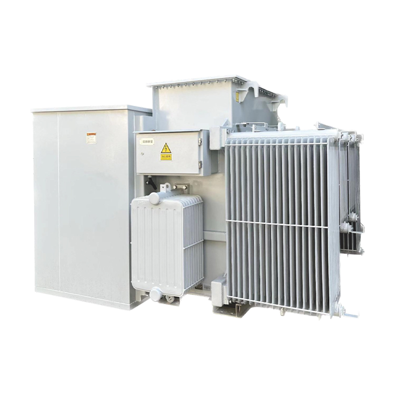
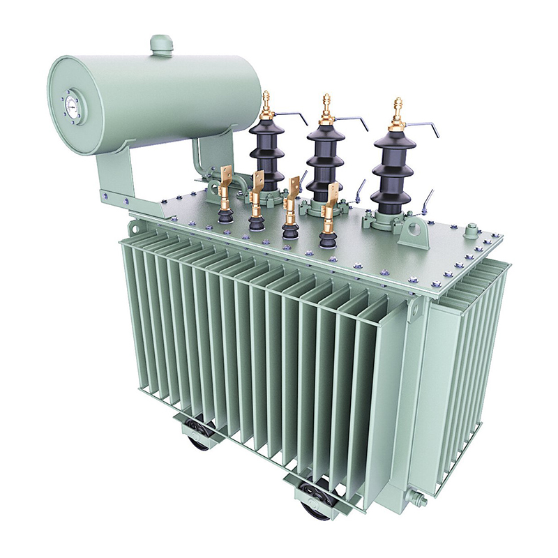
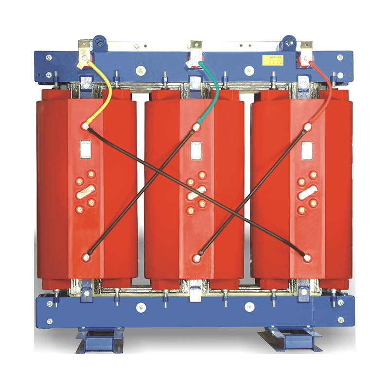
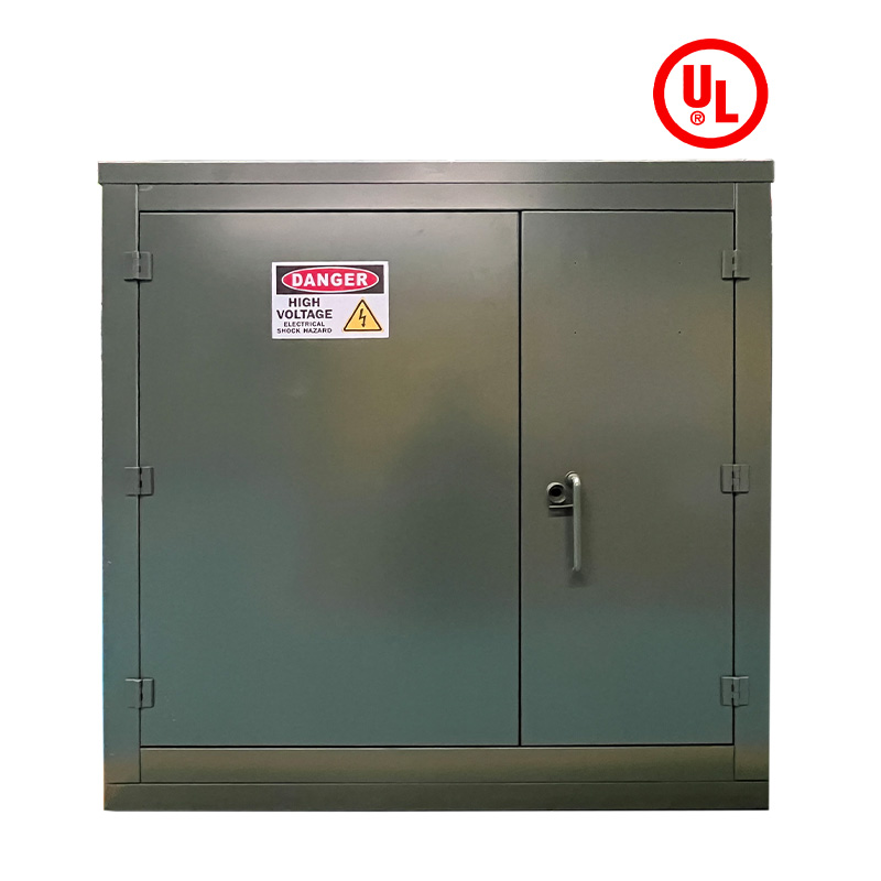
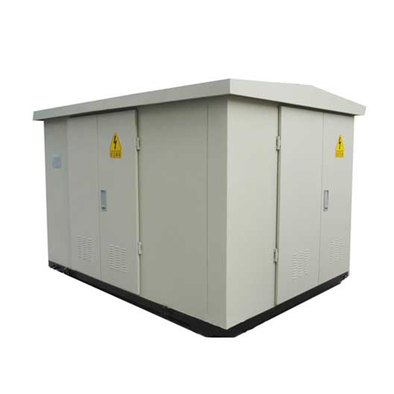
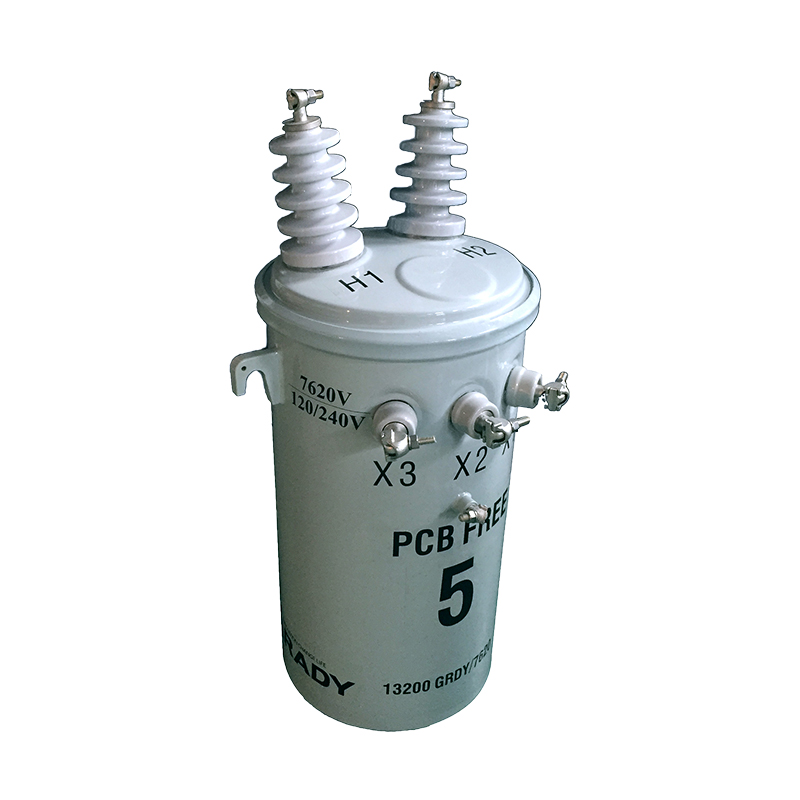
Power transformers are the backbone of electrical grids, facilitating the efficient transmission and distribution of electrical energy. Their reliable operation is critical to maintaining grid stability, preventing blackouts, and ensuring the continuity of power supply to industries, communities, and critical infrastructure. However, transformers are subject to gradual degradation due to thermal, electrical, and mechanical stresses, which can lead to internal faults such as partial discharges, overheating, and insulation breakdown. These faults, if undetected, may escalate into catastrophic failures, resulting in substantial economic losses and safety hazards.
Traditional methods for transformer condition monitoring, such as periodic offline oil sampling and laboratory analysis, have limitations in timeliness and continuity. Offline testing relies on scheduled maintenance intervals, leaving gaps during which incipient faults may develop unnoticed. In contrast, on-line oil chromatography monitoring systems (OCMS) provide real-time or near-real-time analysis of dissolved gases in transformer oil, enabling early detection of internal faults and proactive maintenance. This article explores the principles, applications, benefits, challenges, and future trends of OCMS in power transformer condition monitoring.
Transformer oil serves dual purposes: as an insulating medium and a coolant. When internal faults occur, the insulation materials (mineral oil, paper, and pressboard) undergo thermal or electrical degradation, producing characteristic gases. These gases dissolve in the oil, and their types, concentrations, and ratios provide valuable insights into the nature and severity of the fault.
Different fault types generate distinct gas profiles:
Overheating: Thermal degradation of oil and paper produces gases such as methane (CH₄), ethane (C₂H₆), and ethylene (C₂H₄). High-temperature overheating (above 700°C) may also generate acetylene (C₂H₂).
Partial Discharges: Low-energy electrical discharges decompose oil into hydrogen (H₂) and methane (CH₄).
Arcing: Intense electrical discharges generate large amounts of hydrogen (H₂) and acetylene (C₂H₂), along with trace amounts of ethylene (C₂H₄).
Moisture and Corrosion: Water contamination or metal corrosion can increase hydrogen (H₂) levels.
On-line OCMS continuously extracts oil samples from the transformer, separates the dissolved gases using a chromatographic column, and quantifies their concentrations using detectors (e.g., thermal conductivity detectors for H₂ and flame ionization detectors for hydrocarbon gases). The system then analyzes the gas data against established standards (e.g., IEC 60599, ASTM D3612) to diagnose fault conditions and trigger alerts if thresholds are exceeded.
A typical on-line OCMS comprises the following components:
This unit extracts a continuous or periodic oil sample from the transformer tank or conservator. It includes filters to remove particulates and a pressure regulator to maintain stable flow rates, ensuring representative sampling without disrupting transformer operation.
Gases dissolved in the oil are separated using methods such as membrane permeation, vacuum degassing, or stripping with an inert gas (e.g., nitrogen). Membrane-based systems are widely used for their compact design and low maintenance requirements, allowing selective permeation of gases while retaining oil.
A chromatographic column (packed or capillary) separates the mixed gases based on their affinity for the column’s stationary phase. For example, light gases like H₂ and CO elute first, followed by hydrocarbons (CH₄, C₂H₆, etc.).
Detectors quantify the concentration of each separated gas:
Thermal Conductivity Detector (TCD): Sensitive to H₂, CO, and CO₂.
Flame Ionization Detector (FID): Ideal for hydrocarbon gases (CH₄, C₂H₄, C₂H₂) due to high sensitivity.
Photoionization Detector (PID): Used for trace-level detection of volatile organic compounds.
This unit processes detector signals, calculates gas concentrations, and stores historical data. It communicates with a central monitoring system via wired (Ethernet, RS485) or wireless (4G, LoRa, NB-IoT) protocols, enabling remote access to real-time and historical trends.
Based on predefined thresholds (e.g., gas concentration limits, rate of change, or gas ratios), the system triggers alarms (visual, audible, or digital) for incipient faults. Advanced systems use machine learning algorithms to improve diagnostic accuracy by correlating gas data with transformer load, temperature, and age.
On-line OCMS is widely adopted in various transformer types and grid scenarios, including:
The primary application of OCMS is the early detection and classification of internal faults. By monitoring gas concentrations and ratios, operators can identify fault types (overheating, partial discharge, arcing) and assess their severity:
Case Study 1: A 220 kV transformer in a substation showed a sudden increase in ethylene (C₂H₄) and acetylene (C₂H₂) levels via OCMS, indicating high-temperature overheating. An emergency shutdown revealed a shorted winding, preventing a catastrophic failure.
Case Study 2: A distribution transformer’s OCMS detected rising hydrogen (H₂) and methane (CH₄) levels, consistent with partial discharges. Subsequent offline testing confirmed a degraded bushing, which was replaced before failure.
Continuous gas monitoring provides data for evaluating transformer health over time. Trends in gas generation rates (e.g., increasing CH₄/CO ratios indicating paper degradation) help predict remaining useful life and plan maintenance. For example, utilities use OCMS data to prioritize transformer replacements in aging fleets, optimizing capital expenditure.
In smart grid ecosystems, OCMS data is integrated with SCADA (Supervisory Control and Data Acquisition) and EMS (Energy Management Systems). This enables:
Real-time Grid Stability: Alerts from OCMS trigger load redistribution to reduce stress on faulty transformers.
Predictive Maintenance Scheduling: AI algorithms analyze OCMS data alongside weather, load, and ambient temperature to forecast maintenance needs, minimizing downtime.
OCMS is particularly valuable for transformers in critical or remote locations:
Generating Station Transformers: Connected to power plants, these transformers require 24/7 monitoring to avoid costly outages.
HVDC Transformers: High-voltage direct current (HVDC) transformers operate under extreme conditions; OCMS detects faults in their complex insulation systems.
Offshore Wind Farm Transformers: Remote offshore locations make offline testing logistically challenging, making OCMS indispensable for continuous monitoring.
The adoption of on-line OCMS offers multiple advantages over traditional offline methods:
Early fault detection reduces the risk of unplanned outages and transformer explosions, protecting personnel and equipment. A study by the International Council on Large Electric Systems (CIGRE) found that OCMS reduced transformer failure rates by up to 40% in utility grids.
Reduced Maintenance Costs: Proactive maintenance based on OCMS data avoids unnecessary offline tests and extends intervals between overhauls.
Minimized Downtime: Unplanned outages cost utilities an average of $50,000–$200,000 per hour; OCMS prevents such losses through early alerts.
Optimized Asset Management: Data-driven decisions on repair/replacement extend transformer lifespans, deferring capital investments.
OCMS eliminates human error in manual sampling and provides continuous data, capturing transient faults that may be missed in periodic offline tests. For example, short-duration arcing events during peak load periods are only detectable via real-time monitoring.
Regulatory bodies (e.g., IEEE, IEC) increasingly mandate condition-based monitoring for critical assets. OCMS helps utilities comply with standards such as IEEE C57.104 (Guide for the Interpretation of Gases Generated in Oil-Immersed Transformers).
Despite its benefits, on-line OCMS faces several challenges:
Gas Equilibrium Time: Gases generated in hot spots may take hours to dissolve and reach the sampling point, delaying fault detection.
Sensitivity to Environmental Factors: Temperature variations, oil flow rates, and moisture can affect gas extraction efficiency and measurement accuracy.
False Alerts: Contamination (e.g., air ingress) or system malfunctions may trigger incorrect alarms, leading to unnecessary maintenance.
On-line OCMS installation costs range from $10,000 to $50,000 per transformer, depending on complexity. Regular calibration, membrane replacement, and software updates add to lifecycle costs, which may deter small utilities.
Retrofitting OCMS to aging transformers may require modifications to oil circulation systems. Integrating data with existing SCADA/EMS platforms can also pose compatibility issues, requiring custom software solutions.
Interpreting OCMS data requires expertise in gas chromatography and transformer diagnostics. Many utilities lack trained personnel, leading to underutilization of system capabilities.
Advancements in technology are addressing the limitations of OCMS and expanding its capabilities:
Next-generation OCMS devices are smaller, consuming less power, and suitable for installation in compact transformers (e.g., distribution transformers). Wireless, battery-powered sensors reduce wiring costs and enable retrofitting in remote locations.
AI algorithms are being developed to:
Reduce False Alerts: By correlating gas data with load, temperature, and historical trends, AI distinguishes genuine faults from noise.
Predict Fault Progression: Machine learning models forecast gas concentration trends, enabling precise timing of maintenance actions.
Integrating OCMS with other sensors (e.g., dissolved moisture, oil quality, partial discharge) provides a holistic view of transformer health. For example, combining gas data with dielectric loss measurements improves diagnostic accuracy for insulation degradation.
Industry efforts (e.g., IEC 61850 for communication protocols) are promoting interoperability between OCMS and smart grid systems, simplifying integration and data sharing.
On-line oil chromatography monitoring systems have revolutionized power transformer condition monitoring, enabling early fault detection, proactive maintenance, and enhanced grid reliability. By analyzing dissolved gases in real time, OCMS provides critical insights into transformer health, reducing downtime, improving safety, and optimizing asset management. While challenges such as cost, technical limitations, and skill requirements persist, ongoing innovations in miniaturization, AI, and multi-parameter monitoring are addressing these issues.
As electrical grids become increasingly complex and dependent on reliable power supply, the adoption of OCMS will continue to grow. Utilities and industries that invest in this technology stand to benefit from improved operational efficiency, reduced costs, and a more resilient power infrastructure. The future of transformer monitoring lies in the seamless integration of OCMS with smart grid technologies, paving the way for self-healing grids and predictive maintenance paradigms.


