Load Break Switches: Working Principles and Operational Guidelines
1. Introduction to Load Break Switches
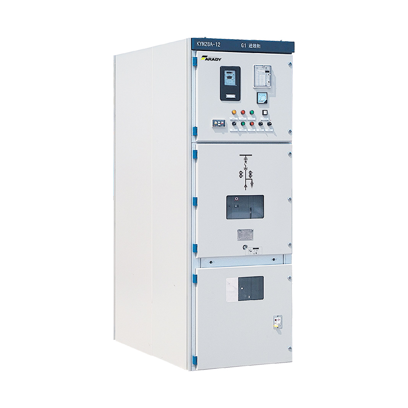
A Load Break Switch (LBS) is a critical component in medium-voltage (1–36 kV) power distribution systems. Designed to safely interrupt load currents under normal operating conditions, it serves as a manual or motor-operated disconnecting device for transformers, capacitor banks, and feeder circuits. Unlike circuit breakers, LBS cannot interrupt short-circuit currents, making it essential to pair them with protective devices like fuses or relays. This article explores the working principles, types, and safety considerations for LBS operation.
2. Working Principles of Load Break Switches
2.1 Basic Structure
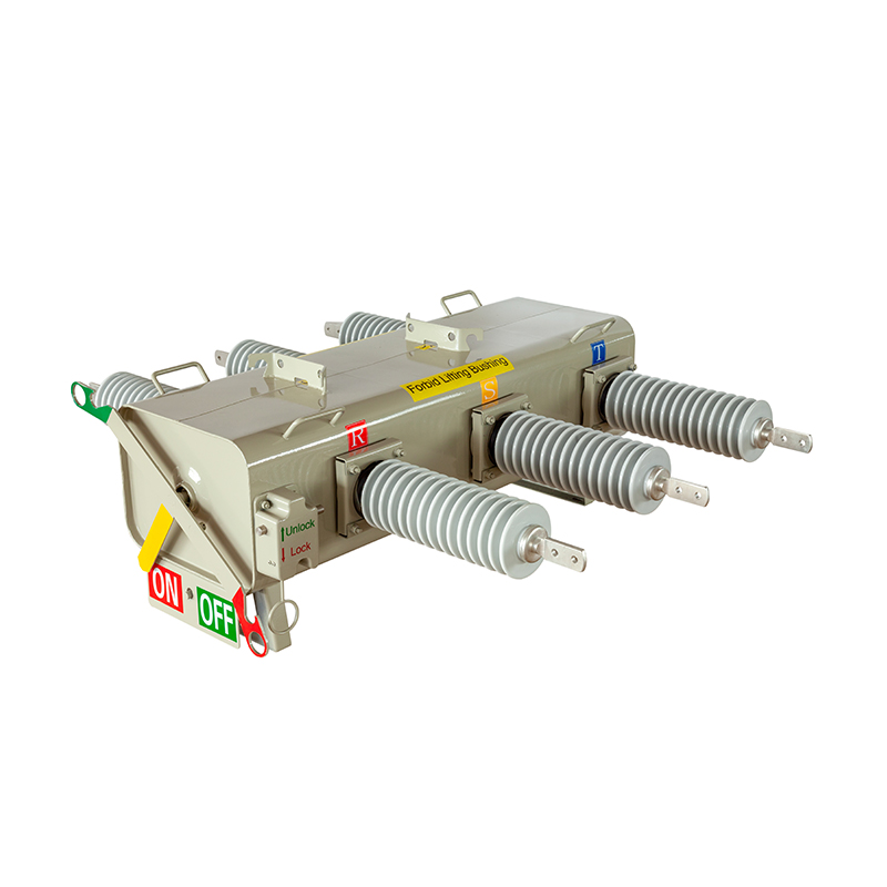
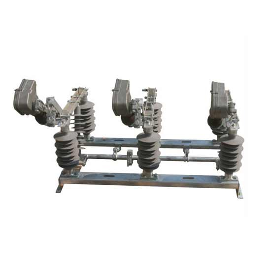
A typical LBS consists of the following components:
Contacts:
Fixed Contact: Mounted on the switch base.
Moving Contact: Connected to an insulated operating rod.
Arc Quenching System: Utilizes air, gas (SF₆), or vacuum to extinguish arcs during switching.
Operating Mechanism: Manual lever, motorized actuator, or spring-assisted mechanism.
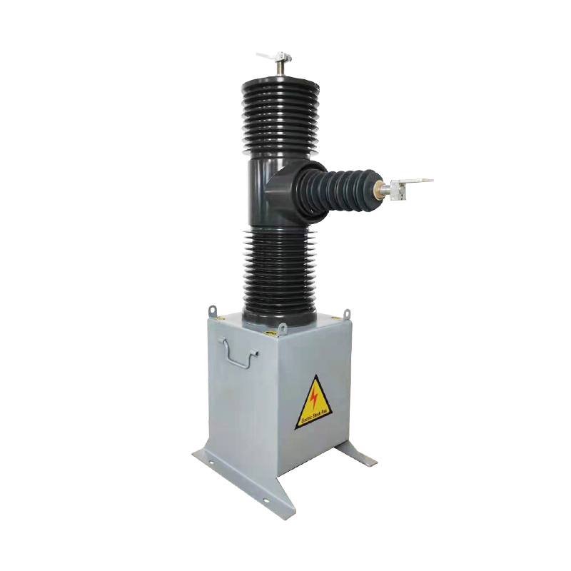
Insulation Housing: Made of epoxy resin or porcelain to withstand high voltages.
2.2 Operating Sequence
Closing the Switch:
The moving contact engages with the fixed contact, allowing current flow.
Ensures low contact resistance to minimize heating.
Opening the Switch:
The moving contact separates, creating an arc due to inductive loads.
The arc is extinguished by the quenching medium (e.g., SF₆ gas deionizes the arc path).
2.3 Arc Interruption Mechanisms
Air-Break LBS: Relies on natural air cooling and contact separation speed.
Applications: Outdoor overhead lines, dry environments.
SF₆ Gas LBS: Uses sulfur hexafluoride gas for superior arc quenching.
Advantages: Compact design, suitable for indoor switchgear.
Vacuum LBS: Employs vacuum interrupters for rapid arc extinction.
Benefits: Maintenance-free, high dielectric strength.
3. Key Precautions for LBS Operation
3.1 Pre-Operation Checks
Voltage Verification: Confirm the circuit is de-energized using a voltage detector.
Mechanical Inspection:
Check for corrosion, misalignment, or wear on contacts.
Ensure smooth movement of the operating mechanism.
Environmental Conditions:
Avoid operating under rain, high humidity, or excessive dust.
SF₆ switches require gas pressure monitoring (≥0.4 MPa).
3.2 Safe Switching Practices
Load Current Limits:
Never exceed the rated breaking current (e.g., 630A for a 12 kV LBS).
For inductive loads (e.g., motors), derate by 20–30% to account for inrush currents.
Switching Sequence:
Opening: Always open under no-load conditions first to verify isolation.
Closing: Ensure downstream devices (e.g., fuses) are functional before energizing.
Arc Management:
Wear arc-resistant PPE (face shield, gloves) during manual operation.
Stand clear of the arc path to avoid exposure to hot gases.
3.3 Coordination with Protective Devices
Fuse-LBS Combination:
Fuses must clear faults within 0.1–0.2 seconds to prevent LBS damage.
Follow manufacturer guidelines for fuse compatibility (e.g., DIN-type fuses).
Relay Coordination:
Set overcurrent relays below the LBS’s short-time withstand current (e.g., 16 kA/1s).
4. Maintenance and Troubleshooting
4.1 Routine Maintenance
Annual Inspections:
Clean contacts with alcohol-soaked lint-free cloth to remove oxidation.
Lubricate hinges and linkages with silicone-based grease.
SF₆ Gas Handling:
Check for leaks using gas detectors; recharge if pressure drops by >10%.
Reclaim gas using EPA-compliant equipment to avoid environmental release.
4.2 Common Faults and Solutions
| Symptom | Possible Cause | Remedial Action |
|---|---|---|
| Stiff Operation | Corroded mechanism | Clean and lubricate moving parts. |
| Excessive Arcing | Worn contacts | Replace contacts or entire switch. |
| Gas Leak (SF₆) | Seal degradation | Replace O-rings and recharge gas. |
| Overheating | Loose connections | Tighten terminal bolts to 25–30 Nm. |
4.3 Safety During Maintenance
Lockout/Tagout (LOTO): Isolate the switch from all power sources.
Discharge Capacitors: Ground capacitor banks before working on connected LBS.
5. Standards and Compliance
IEC 62271-102: Specifies design and testing requirements for AC disconnectors.
IEEE C37.34: Guides field testing procedures for load break switches.
OSHA 1910.269: Mandates safe work practices for electric power generation.
6. Conclusion
Load break switches are indispensable for safe power distribution but demand rigorous adherence to operational protocols. By understanding their working principles, enforcing preventive maintenance, and integrating proper protection systems, operators can maximize equipment lifespan and minimize outage risks. Always prioritize training and compliance with international safety standards to mitigate hazards in high-voltage environments.
Relatenews
- The Application of Load Break Switches in the Robotics Industry 2025-02-28 10:38:00
- The Application of Load Break Switches in the Photovoltaic Industry 2025-02-28 10:36:00
- The Evolution of Load Break Switches in the Age of Artificial Intelligence 2025-02-28 10:30:00
- Load Break Switches: Working Principles and Operational Guidelines 2025-02-27 17:43:00


